


sharing sekalian catatan pribadi …
(campur bahasanya, biar cepet buatnya.. silahkan ditranslate sendiri … copy paste dari bbrp sumber)
Beta Ratio ( β ) is the ratio between the line inner diameter pipe to bore size (innet diameter) of the orifice plate.
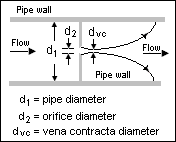
Kalau di rumus kan Beta Ratio = d / D (kalau gmbr di bawah berarti d2/d1)
Orifice
Orifice Plate (plat orifis) sendiri pengertiannya adalah …
plat orifis
—-
(sumber: wikipedia)
An orifice plate is a device used for measuring flow rate. Either a volumetric or mass flow rate may be determined, depending on the calculation associated with the orifice plate. It uses the same principle as a Venturi nozzle, namely Bernoulli’s principle which states that there is a relationship between the pressure of the fluid and the velocity of the fluid. When the velocity increases, the pressure decreases and vice versa.
An orifice plate is a thin plate with a hole in the middle. It is usually placed in a pipe in which fluid flows. When the fluid reaches the orifice plate, the fluid is forced to converge to go through the small hole; the point of maximum convergence actually occurs shortly downstream of the physical orifice, at the so-called vena contracta point (see drawing to the right). As it does so, the velocity and the pressure changes. Beyond the vena contracta, the fluid expands and the velocity and pressure change once again. By measuring the difference in fluid pressure between the normal pipe section and at the vena contracta, the volumetric and mass flow rates can be obtained from Bernoulli’s equation.
Orifice plates are most commonly used for continuous measurement of fluid flow in pipes. They are also used in some small river systems to measure flow rates at locations where the river passes through a culvert or drain. Only a small number of rivers are appropriate for the use of the technology since the plate must remain completely immersed i.e. the approach pipe must be full, and the river must be substantially free of debris.
—
Nah berapa batasan Beta Ratio ini….
cari-cari di mbah google berikut ulasan di salah satu forum http://www.control.com
http://www.control.com/thread/1026239315
surendar on 19 September, 2007 – 1:03 am
Can anybody tell what is the practical significance of orifice beta ratio between 0.3 to 0.7? What will happen if beta ration goes below 0.3 or goes above 0.7?
Rohit Chandak on 19 September, 2007 – 10:38 pm
Beta Ratio is the ratio between the line inner diameter to bore size of the orifice. The flow coefficient is found to be stable between beta ratio of 0.2 to 0.7 below which the uncertainity in flow measurement increases.
A.K.Hait on 20 September, 2007 – 10:39 pm
Interesting question. I don’t have all the books and material at hand now to give a very detailed answer. However, I will try to throw some light on it off my head.
1. Orifice plate flow calculation formula is basically based on empirical formulas based on actual testing. Most of the results are available for beta ratio 0.3 to 0.7.
2. Low beta ratio means the plate has a smaller hole i.e pressure loss will be higher. This may cause higher size of pump and more money.
3. Higher beta ratio increases the discharge coefficient uncertainty. Higher beta ratio means low differential pressure across your orifice and some times may be difficult to measure.
4. Higher beta ratio needs longer staright length.
I remember long time back when we used to do manual calculations of orifice plate bore as per BS 1042, we always tried to keep the beta ratio approx. 0.6. Because near to o.6 beta ratio the discharge point curve is almost flat, so that even if there is some mistakes in your manual calculation, overall accuracy is not affected.
Hope this helps a little!
surendar on 23 September, 2007 – 7:34 pm
thanks for the reply.
Mr. Zack on 17 February, 2011 – 6:31 am
> How do you carry out a manual calculation?
What should I do If my Restriction orifice calculation result is low beta ratio (i.e. 0.1) based on required dP. Note: pressure loss required is fixed. please help.
ken on 13 September, 2011 – 5:34 pm
I am having the same problem.I am using miller to calculate and got beta ratio 0.08.
What will happen if i still design my RO with 0.08 beta ratio result?
Anybody can answer?
Syukri [Control.com Member] on 28 December, 2011 – 10:32 pm
Ken & Zack,
For restriction orifice the limit is the noise generated and vibrations.
We can go to 0.1 beta ratio if the noise is less than 85 dB
Austin on 6 June, 2012 – 5:00 pm
> Can anybody tell what is the practical significance of orifice beta ratio
> between 0.3 to 0.7? What will happen if beta ration goes below 0.3 or goes above 0.7?
Any higher or lower results in too much uncertainty in measurement. For complete calculations and maximum allowable errors, consult the American Gas Association Report No.3 Part 2 “Orifice Metering of Natural Gas and other Related Hydrocarbon Fluids-Specification and Installation Requirements”. That is, assuming this is in relation to a hydrocarbon orifice meter.
David Todd [Author has 2 helpful votes.] on 8 June, 2012 – 12:35 pm
The Beta ratio which you refer to is probably for a Square Edge plate wih flange taps and refers to the allowable Beta limits for the calculation of the orifice size. The Beta limits for the square edge flange taps plate are 0.2 to 0.7 (this may vary slightly depending upon which standard calculation method which you are using). The empirical sizing calculation formulae were determined for the above range of beta. Outside of this limit the formulae are inaccurate and unknown with any certainty. There are a number of different types of orifice plate types available and each type has its own beta limits.
For example square edge corner taps (beta limits are 0.23 to 0.8), Square edge radius taps (beta limits 0.2 to 0.75), Quarter Circle (beta limits 0.25 to 0.6), Conical Entrance (beta limits 0.1 to 0.316).
For Restriction Orifice sizing minimum beta is 0.1 and the maximum beta is not critical.
Ray on 10 October, 2012 – 6:33 am
Nice job man
Bill on 19 October, 2012 – 2:58 pm
Typically, with an orifice computer program designed for sharp edge orifice plates. I play around with the flow and pressure differential to give me a beta ratio of ~.61. Given a fixed pipe size that you are installing the orifice plate in, determine a maximum flowrate that won’t be exceeded. then play around with the differential (usually in inches of water, “WC) to give you a beta between .55 and .70. Typical differentials used are 100 inches and 200 inches.
—
kalau diskusi dengan teman sebaiknya beta ratio diantara 0.25 s/d 0.75 … dia referensi ke ISO berapa gitu (saya lupa euy ..)
—
dari artikel lain
http://saba.kntu.ac.ir/eecd/ecourses/instrumentation/projects/reports/Flowmeter/orifice.htm
The orifice plate is commonly used in clean liquid, gas, and steam service. It is available for all pipe sizes, and if the pressure drop it requires is free, it is very cost-effective for measuring flows in larger pipes (over 6″ diameter). The orifice plate is also approved by many standards organizations for the custody transfer of liquids and gases.
The orifice flow equations used today still differ from one another, although the various standards organizations are working to adopt a single, universally accepted orifice flow equation. Orifice sizing programs usually allow the user to select the flow equation desired from among several.
The orifice plate can be made of any material, although stainless steel is the most common. The thickness of the plate used ( 1/8-1/2″) is a function of the line size, the process temperature, the pressure, and the differential pressure. The traditional orifice is a thin circular plate (with a tab for handling and for data), inserted into the pipeline between the two flanges of an orifice union. This method of installation is cost-effective, but it calls for a process shutdown whenever the plate is removed for maintenance or inspection. In contrast, an orifice fitting allows the orifice to be removed from the process without depressurizing the line and shutting down flow. In such fittings, the universal orifice plate, a circular plate with no tab, is used.
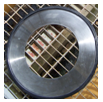
The concentric orifice plate (Figure A) has a sharp (square-edged) concentric bore that provides an almost pure line contact between the plate and the fluid, with negligible friction drag at the boundary. The beta (or diameter) ratios of concentric orifice plates range from 0.25 to 0.75. The maximum velocity and minimum static pressure occurs at some 0.35 to 0.85 pipe diameters downstream from the orifice plate. That point is called the vena contracta. Measuring the differential pressure at a location close to the orifice plate minimizes the effect of pipe roughness, since friction has an effect on the fluid and the pipe wall.
effect on the fluid and the pipe wall.

—
tambahan … artikel dari ISA.org
http://www.isa.org/InTechTemplate.cfm?template=/ContentManagement/ContentDisplay.cfm&ContentID=89033
Sizing orifice plates
Meeting modern expectations
Editor’s noteAs common as flow measurements are using orifice plates, there are various thoughts regarding design, application, rules of thumb, and field practice. Factors that can be considered include measurement errors as % full scale, % rate, bias error, ambient temperature induced errors (largely corrected by smart transmitters), and signal-to-noise ratio deteriorating at low flow rates. InTech invites other thoughtful insights on the subject. |
Fast Forward
|
By Allan G. Kern, P.E.
 |
Orifice plates with differential pressure (DP) transmitters remain the workhorses of fluid flow measurement in the process industries, due to their proven robustness, ease of use, adaptability to a broad spectrum of applications, familiarity, and economy. The weak side of orifice plates, where otherwise properly applied and installed, is limited turndown, with a nonlinear loss of accuracy at lower flow rates due to the square-root nature of the flow/DP relationship.
With modern instrumentation and today’s more stringent demands regarding material balances, yield and loss accounting, energy management, environmental reporting, and safety systems, users have developed greater expectations and requirements regarding accuracy of their flow measurement systems.
When sizing orifice plates, some new rules of thumb can be applied to significantly improve orifice plate turndown and accuracy, while gaining extended measurement range, in most applications. This can be accomplished for the cost and effort of revising the calculation, buying a new orifice plate, and re-configuring the transmitter, activities that are routinely carried out in any case.
Sources of error
There are many potential sources of error in orifice plate flow measurement. Many of them have been minimized in today’s world or are outside of our control, such as variations in pipe diameter, orifice plate machining tolerances, and standardized flange taps. Modern DP transmitters have high accuracy (ca. 0.1%). The greatest sources of error today will come from temperature deviation from design (for liquids) and temperature, pressure, or specific gravity deviations (for gases). The best practice where these parameters vary from design values is online compensation, utilizing built-in control system functions.
The remaining most common source of error is DP measurement error, whether due to transmitter inaccuracy, static pressure effects at high pressures, or imperfect field installation. The effect of measurement error can be greatly reduced by employing appropriate rules of thumb when “sizing” the orifice plate, i.e., when calculating the orifice size, differential pressure, and maximum flow.

Selecting full-scale DP
The orifice flow measurement error figure shows the effect of a 1-inch DP measurement error on accuracy for three different full-scale DPs (50, 100, and 200 inches of water). The square root nature of the relationship amplifies the effect at lower flow rates, making it essential to avoid this operating region. One way to do this is to size the orifice for a greater full-scale DP, which moves the curves downward into the higher-accuracy region in the figure.
Based on an assumption of a potential 1-inch DP measurement error and a goal of less than 2% resultant error in flow (orifice plates are commonly considered “2% devices”), an orifice plate sized for 50-inches full-scale DP (a common design practice) meets this criteria only above 50% of flow, for a turndown of only 2:1. A full-scale DP of 100 inches (the most common design practice today) meets this criteria above 25% of flow, for a turndown of 4:1. And a full-scale DP of 200 inches (an uncommon practice today) meets this criteria above 10% of flow, for a turndown of 10:1.
Faced with today’s more stringent performance expectations, what does the figure say about reducing this error from 2% to 1%? An orifice plate sized for 50-inches full-scale DP only meets this requirement at near full-scale flow (>90%). A full-scale DP of 100 inches only meets this above 50% of flow, or a 2:1 turndown. And a full-scale DP of 200 inches meets these criteria down to 25% of flow, for a turndown of 4:1.
For any given flow, any of these choices is most likely completely acceptable and would likely go unscrutinized, i.e., in most cases, an orifice can be sized for anywhere from 50 to 200 inches full-scale DP, while staying well within the beta ratio and other guidelines. Consequently, based on an often arbitrary choice, turndown can vary from 2:1 to 10:1, and accuracy from 4% or more to 1% or less.

Selecting maximum flow rate
Another often somewhat arbitrary choice in orifice sizing is the maximum flow rate. As this discussion shows, selecting an unnecessarily high maximum flow rate will compromise accuracy at lower (normal) flow rates, so selecting a maximum flow rate based on infrequent conditions carries an accuracy penalty under normal conditions and should be avoided to the extent possible.
Many users do not realize that with modern smart transmitters, which are configured by the end user, not calibrated, the maximum flow measurement limitation is the upper range limit (URL) of the transmitter (often 200 to 500 inches, depending on the make and model), not the configured upper range value (URV), which is the orifice sizing full-scale DP. This removes the incentive to increase the full-scale DP in order to capture infrequent high flow conditions, since the limitation is the transmitter URL, not the configured URV.
Taking advantage of this can have subtle and initially confusing implications on traditional 4-20 milliamp analog input systems, but on digital systems, such as Fieldbus, the practice is simply to configure the control system “high” scale, or URV, equal to the orifice sizing full-scale DP, and set the control system “extended” scale based on the URL of the transmitter. This practice allows the orifice sizing full-scale DP to be chosen appropriately for normal conditions, thereby maximizing accuracy, while taking advantage of the full measurement range of the transmitter to capture infrequent high flow rates.
Modern safety systems also create increased incentive for orifice plate accuracy. Safety system transmitters are traditionally given a reduced range in order to improve accuracy around the trip setting. But in modern safety systems, design calls for the safety transmitters to have the same range as the control system transmitter in order to provide diagnostic discrepancy alarms.
Caveats
There are a few caveats to shrinking the orifice and increasing the DP in order to improve accuracy, but they are not usually significant. As mentioned, the beta ratio, which is the ratio of orifice diameter to inside pipe diameter, should remain within the established design range of ca. 0.3 to 0.7. The table shows increasing the full-scale DP from 50 to 200 inches will decrease the beta ratio from ca. 0.60 to 0.45, still well within range on both ends.

Second, there can be an energy penalty for increased permanent pressure loss, which is typically 50–90% of DP. This amounts to ca. 3 PSIG additional loss when switching from 100 to 200 inches full-scale DP, when at full-scale flow. In most cases, this is not significant, and the pressure is lost elsewhere in the process, for example, across a control valve.
Third, with a higher DP, there is the possibility of cavitation or flashing in liquid service. This is not usually an issue and is typically flagged by the orifice sizing software.
New rules of thumb
For greater orifice plate accuracy and turndown, use a larger full-scale DP. Consider using 200 inches as a default, rather than 50 or 100 inches.
Avoid selecting an unnecessarily high maximum flow for sizing. Utilize the capabilities of modern smart transmitters to capture infrequent high flow rates.
Use the figure to gauge if expected accuracy and turndown are satisfactory, or if improvements could be easily captured by selecting a higher full-scale DP.
ABOUT THE AUTHOR
Allan Kern (allan.kern@yahoo.com) has 30+ years of experience in process control and has authored numerous papers on multi-variable control, inferentials, decision support systems, safety instrumented systems, distillation control, and other topics, with an emphasis on practical process control effectiveness. Kern is a professional control systems engineer in California, a senior member of ISA, and a member of the InTech editorial advisory board.
2012-03-26 06:07:55
REF. pp32-34 “Sizing orifice plates” I think that the article hits some facts but it can not be a new rule of thumb. For some application, e.g. low pressure gas/vapor application, taking a relatively larger full-scale DP such as 200 inches H2O could cause a considerable error in expansion factor and lower its measurement accuracy in totality. Actually, some caveats are addressed in the article but the said point is not. I’m concerned that the article could mislead the reader for some applications like the above cited. less
—
ok, segini dulu …
semoga bermanfaat ..


Tinggalkan komentar